Monday, May 29, 2006

iEEE 1394


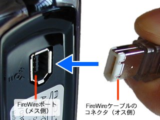
Speed 400 --> 800 mbs
Devices 63 nodes x 16 devices
P'n'p Hot swapable, Hot plugable
Max cable 4.5metres

Rimm 184 RD Ram Rambus


184pin Rimm (PIII & PIV)
2 notch, 16 bit wide
64 bit CPU = 4 x 64bit rimm (Can use 3 dummies)

Ram 184 Dimm - DDR SDRAM


184pin Dimm (PIII & PIV)
1 notch, 64 bit wide
64 bit CPU = 1 x 64bit dimm

Ram 168


168pin Dimm (PII, SDram)
2 notches, 64 bit wide
64 bit CPU = 1 x 64bit dimm

Ram 72 pin


72 pin simm (PentiumI, EDO Ram)
Notch in middle, 32 bit
64 bit cpu = 2 x 32bit

Ram 30 pin

30 pin Simm (386/486)
No notch, 8 bit wide
32 bit CPU = 4 x 8bit simms


Thursday, May 25, 2006

Notes - 25/05/2006 Hardware Troubleshooting

Hardware Troubleshooting


Intellectual Resources FAQs

Knowledge Bases (Microsoft TechNet)

Support Forums

Bug Lists


10 Trouble Shooting Steps

Define The Problem Can you see the problem?

How often does it happen?

Has any new software been installed?

Have any changes been made to the PC recently?


Check The Simple Stuff First Is it plugged in?

Is it turned on?

Is the system ready?

Reseat chips and cables?

Check If It is User Error EEOC Error (Equipment Exceeds Operator Capability)

Reboot The Computer

Determine If The Problem Is Hardware Or Software Related

If The Problem Is Hardware Related, Determine Which Component Is Failing

If The Problem Is Software Related, Try SAFEMODE

F5, F8 during boot

Hold down ’SHIFT’ during boot and drivers will not be loaded

Check Service Information Sources

If It Ain’t Broke… If the change that you make doesn’t work, change back

Ask For Help


Software Troubleshooting

Boot Clean Boot without software drivers (SAFEMODE)

Check OS for Error Messages

Uninstall/Reinstall the application that’s having problems

Look for ways to Repeat the Problem

Install Latest Patches

Check the Internet

Compare and Isolate

NOTE: Windows2000 uses ‘Intellimirror’ and its associated tools to maintain applications – replacing missing files, updating INI or Registry files, or doing a complete installation automatically


Main files used in DOS

IO.SYS First file that loads - Input Output of the system – loads basic drivers - IDE, video, etc

MSDOS.SYS DOS OS – controls file transfer and handling

COMMAND.COM Command interface, gives prompt: C:/>

CONFIG.SYS System Configuration – loads advanced device drivers

AUTOEXEC.BAT Auto runs programmes

MSCDEX.EXE Is the CD-ROM programme. It creates a ramdrive and loads the CD-ROM drivers

IO.SYS, MSDOS.SYS, COMMAND.COM is required

COMFIG.SYS, AUTOEXEC.BAT is extra files


REM Statements ‘rem’ is short for Remark. Used in DOS commands

where you want to stop a command from being initiated


System Resources Available memory should be at about 80% for optimal performance


GPF General Protection Faults

AKA Memory Leaks


The Registry

You can view the Registry by using REGEDIT.EXE or REGEDIT32.EXE (preferred)


POST Routines

  1. The Processor is tested

  2. The ROMs are checked

  3. The DMA controller is tested

  4. The Interrupt controller is checked

  5. The system timing chip is tested

  6. The BASIC ROMS are tested (if they exist)

  7. The video card is checked

  8. Expansion boards are initialized

  9. RAM is counted and tested

  10. The Keyboard is tested

  11. The cassette interface is tested

  12. The floppy drives are tested

  13. Resources are checked and the PC is booted


Common POST Beep Codes

Continuous Beeps Power supply is bad, not plugged into the motherboard correctly or the keyboard is stuck


One Long Beep, Two Short Beeps Video Card Failure


Common POST Error Codes


1** Any number beginning with 1 indicates a system board problem

161 CMOS battery failure

164 Memory size error. Always happens when RAM has been added


2** 2** indicates a memory-related problem

201 Memory test failed, One or more RAM chip found to be bad


3** 3** indicates a problem with the keyboard

301 Keyboard error.


4** Monochrome video problems

5** Colour video problems


6** Floppy disk system problems

601 Floppy error – adapter or driver failure, cable problems


17** Hard disk problems.

1780 Drive 0 (C:) has failed

1781 Drive 1 (D:) has failed

Motherboard

NLX
AT, ATX & NLX

Dos


Tuesday, May 23, 2006

Notes - 23 May

PC Peripherals

Hot Swappable
SCSI only, not IDE
Swap drives while the PC is still running (known as hot-swap)

Hot Pluggable
Plugging cable into a device and PC while the PC is still running - USB


Upgrading BIOS Follow the instructions
EEPROM (Electrically Erasable Programmable Read Only Memory) used in Flash-able ROMs (CMOS)


Laptop Power Sources

NiCad Nickel Cadmium
Subject to Memory Effect

NiMH Nickel Metal Hydride
Dose not suffer from Memory Effect
About 10% more power than NiCad
Only lasts for 400 charge cycles

LiON Lithium Ion
Does not suffer from Memory Effect
10% more power than NiCad
LiON requires that laptops have special control circuitry and they are more expensive than NiCad NiMH
Only lasts for 400 charge cycles


Fuel Cells A device that produces power from the electrochemical or catalytic breakdown of some chemical substance (usually hydrogen or hydrocarbon), with water vapour as the only emission


Modems

External Modem Use an existing serial port, so they don’t have the configuration problem with IRQs and I/O addresses.

UART (Universal Asynchronous Receiver/Transmitter)
The chip that manages the serial data that’s moving in and out through the serial port.
If the modem is 9600bps or faster, you need to use a 16-bit UART for example the 16450 or 16550 models
(16550 has a transfer rate of 115,200bps)

External Modem Lights
OH Off Hook Modem is dialing or has the phone off the hook
SD(TX) Transmit Data (Modem transmits)
RD(RS) Receive Data (Modem receives)
AA Auto Answer (Auto pick-up)
RTS Request to Send


Cable Modem Used to connect PCs and other devices to a cable television

DOCSIS (Data Over Cable Service Interface Specification)
Specifies how to allow data services over a cable system


COM PORTS IRQ Addresses I/O Address
COM 1 4 3F8-3FF
COM 2 3 2F8-2FF
COM 3 4 3E8-3EF
COM 4 3 2E8-2EF


PDA (Personal Digital Assistant)
The PDA must have a method of connecting to the PC, most often this is done through serial or USB
Also, pieces of software known as conduits facilitate the communication between software on the PC (like Outlook) and the apps on the PDA


UPS: Uninterruptible Power Supply
Replaces line power if interrupted with no break in supply
SPS: Standby Power Supply
Like a UPS but the ‘wall’ powers the PC directly

EMI: (Electromagnetic Interferrence)
Caused by the electrometic waves emmited in motors in appliances

RFI: (Radio Frequency Interference)
Higher-frequency version of EMI

Line Conditioners Devices used to clear up problems with EMI and RFI

Spike Power overage condition that lasts for an extremely short amount
of time

Surges The result of faulty transmission equipment at power stations or lighting strikes
Surges last longer than Spikes

Sag A momentary drop in voltage, lasting a few milliseconds

Brownout Occurs when voltage drops below 220v for a second or more

Blackout Occurs when power drops from 220v to 0v in a short time period


Optiming PC Performance

Air Cooling CFM (Cubic Feet Per Meter)
Liquid Cooling Achieves better cooling performance than Aip Cooling
Much more expensive than Air Cooling
Phase Cooling Change liquid to gas through 'Phase Change'
Achieves CPU temputures of -20C


Preventing ESD CMOS chip most likely to suffer from ESD
ESD perfers a cool and dry environment


Anstistatic Wrist Strap Uses a 1-megaohm rersistor to bleed charge away


Fire Safety Types of Fire Extingushor
A: Water-based extingushing material for wood and paper
B: Carbon Dixode for flammable liquids
C: for electrical fires
D: Metal powder or NaCl (Salt) for flammable metals like phosphorus and sodium


The monitor: Do not try to repair the monitor, but if you do, use
'High-Voltage Probe' that bleeds voltage


Cleaning Systems Clean a monitor with a damp cloth. Not cleaners
Clean a keyboard by soaking it in distilled water and drying it off therefor removing the impurities
Electronic connectors are cleaned by using a swab moistoned in distilled, denatured isopropyl alcohol
Use compressed air to clean the inside of PCs

Monday, May 22, 2006

Resistance The electrical property most commonly measured in troubleshooting components

Measured on ohms
A measurement of infinite resistance, in other words, indicates if electricity can flow through a wire

If the reading is infinite, no electricity can flow, meaning there is a good chance that the cable is broken


Thermal
Compound
The amount of compound is critical, too much and you won’t get good heat transfer;
too little and you won’t get good heat transfer

There should only be a very thin layer of compound on the die


Airflow There is an ideal airflow path in PC cases, from front to back,

cooling the areas of the board that most need airflow


Testing CMOS Configuration Has Changed Error (or similar)
This is normal. Your PC is saying that new devices or memory have been attached
One Long Beep, Three Short Beeps, and No Video

Typically a memory failure (memory not installed or seated properly)

Computer Powers Up for a Moment, and then Powers Down
and Will Not Turn Back
On until you Unplug It

Usually caused by CPU fan that won’t turn on, isn’t at the right speed or is the kind that can’t send info to the motherboard


A Loud Bang, Smoke, or both at the Back of the Case

PSU was set to wrong voltage


The PC is on, But No Video on the Monitor and you hear One Beep

The video card is probably not seated probably


No Video and You smell Burning Silicon

Chances are the manufacturer has installed the BIOS chip incorrectly, causing a short.

The chip has burned up on power up.


FRU Field Replaceable Units

Those units (components) that can be replaced in the field (wherever the PC is)


Bad Pixels With LCDs sometimes defects occur where you get a non-responsive pixel, caused by a corresponding faulty transistor


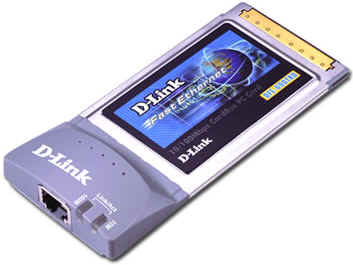
PCMCIA Personal Computer Memory Card International Association

Also called PC Card

32-bit Bus Width, bus speed form 8MHz to 33MHz (PCMCIA version 3)


Type 1: 3.3mm thick and are most commonly used as memory cards

Type 2: (5mm) Used mostly as modems or LANs

Type 3: Slot is 10.5mm thick. Commonly uses as PC Card HDDs


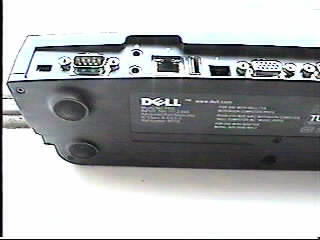
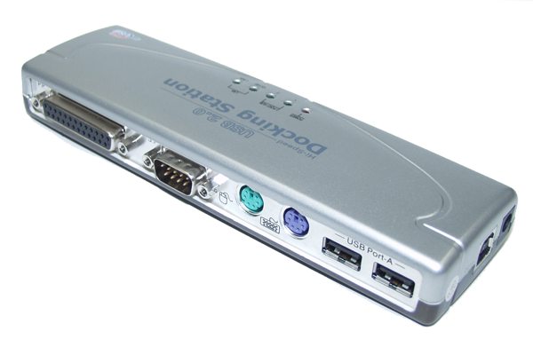
Docking A Docking Port is used to connect a laptop to a special laptop-only parpherial - a

Station Docking Station. A Docking Station can contain a full size expansion bay, expansion bus

slots, can connect to full size keyboards, printers, etc,

Docking Stations are proprietary hardware, usually pacifically to the make and model of the laptop


    1. 802.11b: operates at either 1Mbps or 11Mbps over 2.4GHz radio frequency band

802.11g: dame frequency band but operates at: 1Mbps, 11Mbsp, 54Mbps

Docking station


Pcmcia


Friday, May 19, 2006

Notes 18-05 Networks

Cabling

Coaxial Plenum-Rated – coating does not produce toxic gas when it burns
Coaxial cable is rated according to RG-type
Nost common - Thinnet or Cheapnet (Ethernet 10Base2 cable)

RG-8 Thicknet 10Base5 Solid copper
RG-58 AU Thinnet 10Base2 Stranded copper

Connectors: BNC (male/female connectors, T-connectors, barrel
connectors and 50-ohm terminator cap)

Vampire Tap: used with Thicknet – uses 15-pin AUI connector
Cable than runs from AUI port is a DIX cable (aka Transiever cable)


Twisted-Pair Extremely popular

STP/UDP Shielded twisted-pair/Unshielded twisted-pair

Category 2 4Mbps (8 wires/4 twisted pairs)
Category 3 10Mbps (8 wires/4 twisted pairs, 3 twists per
foot)
Category 4 16Mbps (8 wires/4 twisted pairs, 3 twists per
foot)
Category 5 100Mbps (8 wires/4 twisted pairs, 3 twists per
foot)
Category 5e 1Gbps (8 wires/4 twisted pairs, more than
3 twists per foot)
Category 6 1Gbps+ (8 wires/4 twisted pairs, 3 twists but
are oriented differently than others)

Uses RJ connectors – RJ11 or RJ45


Fibre-Optic Made of Thin, flexible glass or plastic fibre surrounded by a rubber
coating. Immune from electrical or radio interference. High cost
100Mbps to 1Gbps over a distance of several miles
Single-mode (3,000 meters) or Multimode (2,000 meters; multimode signal degrades quicker and has lower available bandwidth)
Connectors: SC (Square) Connector
ST (Straight Tip) Connector
Both a good for 1000 matings


RS-232 Serial Cable
Can connect into a Multiplexer (like a Hub but for serial)


Wireless Infrared light, laser, narrow-band, microwave, spread-spectrum
radio


NIC (Network Interface Card)
Half-Duplex/Full-Duplex
HD: Cannot send and recive data at the same time
FD: Can and recive data at the same time
NIC Configuration – IRQ Address, I/O Address, DMA Address
‘Link Light’
Media Access Methods – CSMA/CD, CSMA/CA, Token Passing,
Polling


Connectivity Devices

Repeaters Amplifies voltages (signal) between similar network segments
Not only boosts single but also the noise.
Works on the Physical layer of the OSI model (ex: 10BaseT)
Hubs are multi-port repeaters
5-4-3 Rule: 5 Network Segments-4 Repeaters-3 Segments can be populated


Hubs Provides a physical, electrical station to all connected ports. Sends
information unintelligently to all connections (except sender)

Active Hubs: Amplify and some cleanup signal
Passive Hubs: Connect all ports electrically


Switches Works on Data Link Layer of the OSI model (some work on level
3)


Bridges Works on the Data-Link layer of the OSI model.
Join similar topographies and divides network segments
Bridges are not able to distinguish 1 protocol from another
Bridges can filter out noise


Routers Works on the Network later of the OSI model


Brouters Combined Bridge and Router – Used to connect dissimilar network
segments and also to route one specific protocol


Gateways connect dissimilar network environments and archetures
For example – Windows NT to Novell NetWare
Some gateways can use all 7 OSI levels, but frequently run on the
Application level.

Thursday, May 18, 2006

Gateways

HUbs switch bridge etc

Networks have the trend to grow, requiring often the need for repeaters ( on 10base2 - Thin-Ethernet ) or multiple hubs (on 10/100baseT Twisted-Pair), where it is required to follow the rules on maximum number of Repeaters/Hubs ( Large Networks: 5-4-3 Rule ).
This includes today also the possibility to connect systems without cables using a
WLAN AccessPoint.

10base2 - Thin Ethernet (Coax):


10baseT - Twisted Pair (TP/UTP):


But these 'cable-extension' method have all a serious limitation
concerning the maximum throughput of the network:
(explanation is visually via the animated GIF below)

Hubs and repeaters are fairly simple, 'non-intelligent' devices:
whatever comes in on one port, gets amplified and send out to ALL other ports, so any network transmission 'fills up/flows into' ALL cable-segments of the network, so only ONE network connection can be active at a time on the complete network !


When multiple system try to communicate at the same time:
(explanation is visually via the animated GIF below)

then the signals 'collide'/corrupt each other, making them invalid, time has been wasted and the system will try after a random delay again to transmit, resulting in network slowdown.


There is a possibility to optimize such network configurations:
Bridge:
In the early days of networking, such a 'intelligent' device called 'Bridge' viewed at the data inside the transmissions, to find out based on the Network-card addresses (MAC), whether it is necessary to transmit the information to a different segment or not. Such Bridges has only 2 connectors, allowing to split large networks into 2 smaller sub-networks.

Switch:
Switches are also 'intelligent', but are able to handle more than 2 ports and are able to handle more than 2 communications at the same time:
When a transmission comes in on one port, the switch looks at the MAC addresses to determine, onto which port to send it out:

Now a large network can handle MULTIPLE transmissions at the same time:
(explanation is visually via the animated GIF below)


But to be able to get this additional Through-put, careful planing of the network layout is required, looking on the flow of the network traffic:

Singe Server configuration:

Swapping a hub to a Switch in such a configuration will not optimize the network, since the connection from the TP-HUB to the server is still the bottle-neck.

Multi Server configuration:

If most the network traffic is within the workgroups (departments,..) and only few network traffic is between the workgroups, then a Switch is the solution to optimize network utilization.


Optimize 10 Mbit Network using a 100 MBit Server connection:

Blackbox = Hub
if the 'Blackbox' is a hub (even if it is a switching 10/100 Mbit hub), the throughput of the complete network is limited at 10 Mbit (since ALL traffic is transmitted by a hub to ALL connected segmentsand even a 100 Mbit connection
from the hub to the server results to a very limited improvement )
:


Blackbox = Switch
if the 'Blackbox' is a Switch, then each connected system can communicate at full speed of the 10 Mbit with the server ( because the switch does NOT pass it through to the other 10 MBit segments and the connection of 100 MBit with the server can handle the higher throughput)


In reality, a server is handling multiple network requests at the same time,
which makes the use of a Switch and a 100 Mbit link between the switch and
the server even more efficient:


Since changing of 10 MBit TP-cabling to 100 Mbit/CAT5-cabling is expensive
in offices (where cables run inside walls and across sealings), swapping a
10 Mbit HUB to a 10/100 MBit SWITCH and upgrading the connection to the
server to 100 Mbit is a cost-effective solution to improve network throughput.

Repeaters Hubs Switches Bridges


Repeaters

One distance limitation in LANs arises because electrical signals become weaker as they travel along a cable. Some LAN technologies allow two cables to be joined together by a device called a repeater. When a repeater detects a signal on one cable, it transmits an amplified signal on the other cable. This is illustrated in Figure 2.

Single repeater
Figure 2: Single repeater

The repeater connects directly to the Ethernet segments, without the use of a transceiver. The maximum size of an Ethernet segment is 500 m, so a single repeater can double the effective length of an Ethernet to 1,000 m. Unfortunately, this cannot be continued indefinitely! The Ethernet standard requires low delay for CSMA/CD to work; if the delay is too large, the scheme fails.

The inventors of Ethernet envisaged its deployment in an office building with two Ethernet segments on each floor and an additional vertical segment connecting the floors, so they put a limit of four repeaters in an Ethernet. This architecture is illustrated in Figure 3.

Multiple repeaters
Figure 3: Multiple repeaters

In this Figure, no two stations are separated by more than two repeaters. Increasing the sizes of the segments by adding an additional repeater per floor would mean that no two stations are separated by more than four repeaters.

The most important disadvantage of a repeater is that it does not understand frames, it simply amplifies the electrical signal. Therefore, if a collision or electrical interference occurs on one segment, repeaters cause the same problem to occur on all other segments.


Wireless

http://www.os2warp.be/index2.php?name=wifi